
MINI PADDER
Conveyor
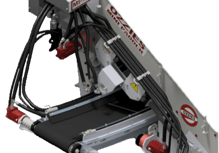
Inside the cabin, sophisticated control mechanisms grant comprehensive oversight over the rotation direction, velocity, and maneuvering of the Mini-padder conveyor. These nuanced controls enable exact modulation of the screened material's flow.
For enhanced mobility, the conveyor has been engineered to fold seamlessly, particularly beneficial for transportation and navigation within restricted environments, subsequently minimizing deployment durations.
The conveyor's lateral movement is governed by a dedicated motor, ensuring precision in material placement within the ditch. The conveyor's distinctively architected contour optimizes the dispersion radius of the material.
Controls
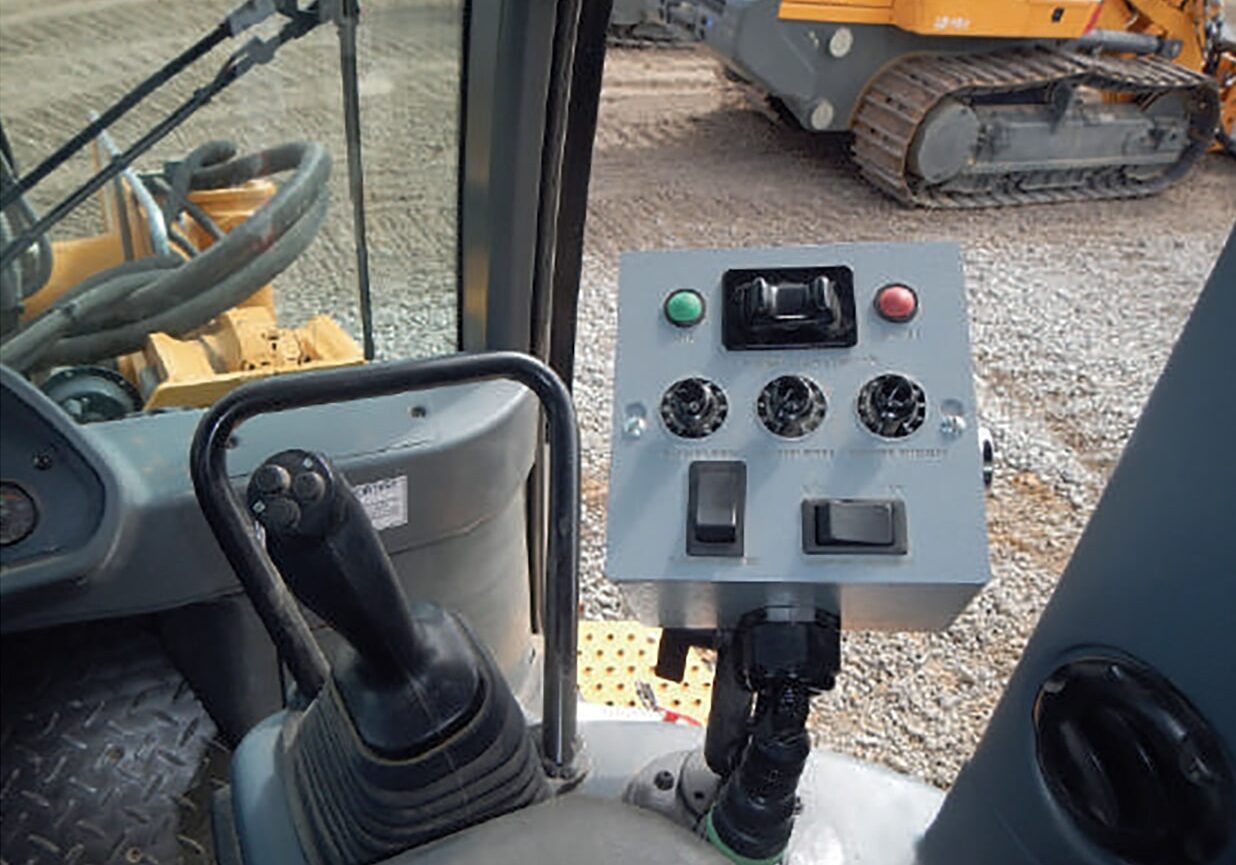
The controls for Ozzie's MINI PADDER are strategically located on the dedicated control box, adjacent to the loader arm control mechanisms.
This control box hosts an array of meticulously labeled operational components:
- Master Hitch Pin Activation
- Master Hitch Depin Functionality
- Conveyor Lateral Movement Toggle Switch
- Elevator Speed Variability Dial
- Conveyor Speed Adjustment Interface
- Vibrator Intensity Modulation
- Temporary Elevator Reversal Toggle Switch
- Conveyor Directional Toggle Switch
Elevator
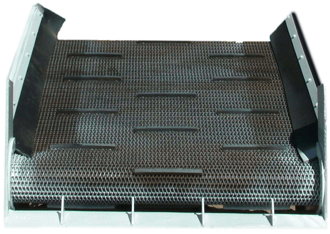
Through meticulous engineering and exhaustive testing, we guarantee that Ozzie's MINI PADDER screens precisely to the stipulated dimensions. Our proprietary adjustable elevator drive system is designed to provide consistent chain engagement, significantly minimizing undesired shifts and slips.
Externally positioned variable chain adjusters on the padding head facilitate optimal chain tension management, especially in challenging terrains. Furthermore, the integrated chain vibrator, which can be activated instantaneously, is adept at screening dense or moist materials, while simultaneously dislodging debris from the chain.
Machine Specifications
Style: Liebherr D934 L A6 diesel engine.
Net Power ISO 9249: 175 HP (129 kW).
Net Power SAE: 173 HP (129 kW).
Displacement: 427 in³ (7.0 L).
Operating Voltage: 24 V.
Alternator: 80 A, Heavy Duty.
Rated Speed: 1,800 RPM.
Fuel System: Modular Unit-Pump-System (UPS) direct high injection pressure fuel system, precision timing controlled fuel dispersion via ECU.
Starter: 10 HP (7.8 kW).
Batteries: 2 x 170 Ah / 12 V.
Air Cleaner: Dry-type air cleaner, pre-cleaner, automatic dust ejector, radial seal for main and safety elements.
Cooling System: Combination cooler with single units for water, hydraulic oil, fuel, and intake charge air. Hydrostatic and thermostatic cooling fan.
Engine Lubrication: Pressurized lube system; Features powerful pump and deep oil pan for guaranteed lubrication up to 45°.
Design: 4 in-line cylinders, intern exhaust gas recirculation AGR, turbocharger, air-to-air aftercooler, single-cylinder, gear water pump, fuel pump, and oil pump.
Machine Hydraulics: Load-sensing proportional pump control, built-in check valves, hydraulic quick disconnect couplings.
Pump Type: Electronically controlled, variable output pump, swash-plate design.
Maximum Pump Flow: 55.2 US gal/min (209 L/min).
Pressure Limitation: 3,770 PSI (260 bar).
Filter System: Tank return filter with a magnetic rod. High-pressure filter on attachment supply.
Control: Joysticks mounted on either side of the operator chair. No pedals. The right joystick controls loader arm movement and attachment tilting. Automatic magnetic hold buttons activate bucket float, bucket positioner, and lift kick-out pre-set functions. The left joystick controls travel, turning, and reversing. Release the joystick to the neutral position to enable the brake.
Valve Type: Load-sensing 4-bank proportional valve stack.
Pressure Limitation: 2,800 PSI (193 bar).
Filter System: High-pressure filter on the supply line.
Quick Couplers: Four bulkhead-mounted quick-release hydraulic couplers to disconnect lines from the loader; tethered caps to seal open lines.
Controls: Control box mounted beside loader arm joystick. Programmed logic controller interfacing between control box and proportional valve.
Hydraulic Functions: Hitch pin engage/disengage, variable elevator speed, momentary elevator direction, variable conveyor shift, variable vibrator speed.
Cooling: Dedicated hydraulic fan cooler.
Lifting: 6.4 seconds
Attachment tilting: 2.2 seconds
Lowering: 2.8 seconds
Total cycle time: 8.1 seconds
Drive system: Independently driven tracks. Closed-loop infinitely variable hydrostatic travel drive, powered by two axial piston variable displacement pumps and motors in swash-plate design.
Travel speed: Infinitely variable electronic-controlled. Work Speed: 0 - 4.0 mph (0 - 6.5 km/h) | Travel speed: 0 - 6.2 mph (0 - 10 km/h).
Load sensing system: Electronic engine speed sensing control (load-sensing feature) automatically adjusts travel speed and drawbar pull to match changing load conditions.
Cooling system: Hydraulic oil unit built-in combination cooler.
Service brakes: Hydrostatic, the dynamic braking effect from the travel drive system.
Parking / Emergency brake: Multi-disc brake, wear-free, automatically applied with neutral joystick position.
Steering: Hydrostatic, unlimited maneuverability for full power turns and counter-rotation.
Final drive: Combination spur gear with planetary gear, double sealed (duo cone seals) with electronic seal-integrity indicator.
Control: Single-lever travel control for all travel and steering motions and counter-rotation.
Filter system: Micro cartridge filters in the cooling circuit.
Heating & A/C system: Pressurized with fresh air intake, recirculation air filter, 12 louvered vents for all temperature-controlled cab areas, sliding side windows left and right.
ROPS / FOPS cab: Roll-over Protective Structure (ROPS) according to EN ISO 3471. Falling Objects Protective Structure (FOPS) according to EN ISO 3449.
Operator seat: Adjustable suspended seat adjustable to the operator's weight.
Monitoring system: Analog and digital instrument panel. LCD screen for engine, RPM, travel speed, and service codes. Automatic monitoring of operating pressures, temperatures, and fill levels. Hour meter gauge.
Titling system: Max 40° to rear with the hydraulic hand pump.
Chains: Sealed and lubricated, track chain tension via grease tensioner and hydraulic cylinder.
Chain links: 38 on each side.
Sprocket segments: 5 on each side.
Track rollers: 6 on each side.
Carrier roller: 1 on each side.
Track shoes: 20 in (508 mm), double grouser.
Track shoes optional: 22 in (560 mm), double grouser | 24 in (610mm), double grouser.
* Wider shoes available on demand
Grouser height: 1.67 in (42.5mm).
Mount: Pivot shafts and equalizer bar (cushion mounted).
Fuel tank: 95.1 US gal (360 L).
Cooling system: 9.5 US gal (36 L).
Engine oil with filter: 7.9 US gal (30L).
Spiltter box: 0.8 US gal (3.1L).
Hydraulic tank: 21.9 US gal (83L).
Pivot shaft, each: 1.3 US gal (5L).
Final drive, each: 5.3 US gal (20 L).
Duo cone seal, each: 0.9 US gal (3.3L).
Design: Self-loading, self-screening, variable speed hydrostatic system. The Spill belt transports fines to the conveyor system.
Controls: Cab-mounted control box. The potentiometer dial controls speed. The momentary rocker switch reverses the elevator direction.
Screen: 3/8 into 1½ in (9.53 mm to 38.1 mm), screening area of 310 ft² (28.8 m²).
Vibrator: Dual roller vibrating system. Variable speed control loosens debris and increases output.
Elevator belt: 60 in (1,524 mm) wide v-groove transfer belt under the lower half of the screening area.
Rated shaft speed: 300 rpm.
Design: Multi-directional, variable-speed hydrostatic system. Arched design for increased ground clearance and improved material throwing distance.
Controls: Cab-mounted control box. Potentiometer dial control speed. The three-position rocker switch selects left, right, or off rotation. Center sprung joystick controls left and right conveyor shift function.
Conveyor belt: 16 in (406 mm) wide v-groove belt.
Features: 42 in (1066.8 mm) lateral slide. The conveyor section can be folded to reduce the transport footprint to 97 in (2463.8 mm) total width.
Rated shaft speed: 775 rpm.
Machine Dimensions
Padder Dimensions
Main Applications
The MINI PADDER has been engineered to facilitate precise backfilling of narrow-diameter trenches, ranging from 3 to 10 inches (76 to 254 mm) in diameter.
Backfill separation is a critical practice in distribution cable projects, contributing to electrical distribution systems' reliability, safety, and cost-effectiveness. It ensures the proper installation and maintenance of cables, minimizes the risk of cable damage, supports erosion control, facilitates environmental compliance, and enhances overall project efficiency.
Transport to different job sites and increase operational efficiency by reducing the need for material transportation and processing at a central facility.
Backfill separation plays a crucial role in renewable construction, maintenance, and environmental compliance. It enhances the stability and longevity of foundations, reduces cable damage risks, mitigates erosion, and contributes to cost-effective and environmentally responsible renewable operations.